Charge Controller Types
Introduction
This section will go over charge controller types and their purpose. We will look at the benefits of each controller and why one is better in a certain situation that another. We will also look at sizing different kinds of controllers. The charge controller is an essential component to every off-grid system. In fact, we do not recommend using an off-grid system unless you have a controller, and there are a lot of good reasons why. Charge controllers generally come in PWM and MPPT.
Charge Controller Function
The main purpose of the controller is to prevent the batteries from over charging. The controller directly reads the battery level, and once the battery is full, it knows to slow down the rate of solar charge to a float, keeping is from charging the batteries past 100%. This is important as overcharging the batteries can potentially ruin them.
Another purpose of the controller is to charge the batteries at the correct voltage level. This helps preserve the life and health of the batteries. Also, some controllers have special characteristics which allow you to wire your panels in a special way to achieve your charging goals.
PWM Charge Controller Function
PWM stands for Pulse Width Modulation, which stands for the method they use to regulate charge. PWM controllers have the more basic charging feature in the sense that they mainly just drop the voltage coming from the panel to charge the batteries. This drop in voltage equates to a loss in wattage, in the case of the PWM causing a 75-80% efficiency.
PWM Charge Controller Sizing
A PWM controller will have an Amp reading for it, for example 30 Amp PWM Controller. This represents how many amps the controller can handle, in the case above, 30 amps. Generally the two things you want to look at for a PWM controller is the amperage and voltage rating.
Please take a look at the following controller electrical specifications
Model 2.5.1
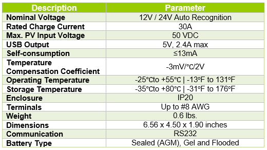
Firstly we want to look at the nominal system voltage. This will tell us what voltage battery banks the controller is compatible with. In this case, you can use 12V or 24V battery banks. Anything higher, such as a 48V battery bank, the controller will not be able to work on.
Secondly we look at the rated battery current. We will use the above model in the chart as an example, in which case it has a 30 Amp rating. We recommended a factor of safety of at least 1.25, meaning you would multiply the current from your panels by 1.25 and then compare that to the 30 amps. For example, 5 100 Watt panels in parallel would be 5.29 x 5 = 26.45 Amps. 26.45 Amps x 1.25 = 33 amps and would be too much for the controller. The reason for this is the panel can experience more current than it is rated for when insolation is above 1000 Watts/m^2 or tilted.
Thirdly we will look at the Max. Solar Input. This tells you how many volts you can have going into the controller. This controller cannot accept more than 50 V in. Let’s look at having 2 x 100 Watt panels in series for a total of 22.5V (open-circuit voltage) x 2 = 45 volts. In this case, it will be ok to wire these two panels in series.
Fourthly we can look at the Terminals. Each controller will usually have a maximum gauge size for the terminal. In the case of the controller we are looking at, it can handle up to #8 AWG. This is important when purchasing wiring for your system.
Fifthly we can look at Battery Type. These tells us what batteries are compatible with the charge controller. This is important to check as you don’t want to have batteries than cannot be charge by the controller unit.
MPPT Charge Controller Function
MPPT stands for Maximum Power Point Tracking, which stands for the method these use to regulate charge. MPPT charge controllers use this method of charging, which essentially finds out at any given condition, what is the maximum operating point for the panels current and voltage. With this method, MPPT controllers are actually 94-99% efficient.
MPPT controllers have two special features about them that will be mentioned in the MPPT Charge Controller Sizing section. One is that they can accept a high input voltage and step this voltage down to match your battery bank voltage for a correct charge. Two is that even though they lower the voltage, they are able to recover any potential lost power via a boost current, which increase the amperage to make up for the lost voltage.
MPPT Charge Controller Sizing
MPPT Controllers will have an Amp reading for it, for example a 40 Amp MPPT Controller. They will also have a voltage rating, but unlike PWM the input voltage rating is much higher than the battery banks it will charge. This is due to the special property of the MPPT controller being able to lower the voltage to the battery bank voltage and then increase the current to make up for lost power. You do not have to utilize the high input voltage if you want to avoid series connections in small systems, but it is very beneficial in larger systems.
Please take a look at the following controller electrical specifications
Model 2.5.2
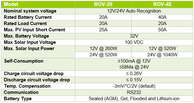
Firstly we can see, as we did before, that his controller can handle 12V or 24V battery banks.
Second, we will be looking at the Rov-40, which is rated for 40 amps of current.
Thirdly we can look at the Max Solar Input Voltage, in this case 100 Volts. This particular MPPT Controller can accept 100 Volts input. It will then take this (up to) 100 Volts and step it down to your 12V or 24V battery.
Let’s take an example of a 400W system in series. You have 4 x 100 Watt panels, each with an open-circuit voltage of 22.5V. Those 4 in series will be 4 x 22.5 V = 90 Volts, which the controller can accept. Now if we ignored boost current, we would see that string only has 5.29 amps, so then if the controller is 40 amps, couldn’t we have (40/5.29 = 7.5) 7 strings, bringing us 2800 Watts? Why does the spec sheet say 520 W maximum? To answer this, we need the boost current.
Boost current can be calculated by taking the system array wattage divided by the battery bank voltage. In the case of 2800 Watts we have 2800 Watts / 12 V = 233 Amps, which would destroy the controller. Realistically we find that 520 Watts / 12V = 43 Amps. We can ignore this result as 12V is a voltage you will probably never see. More accurately you would divide by boost voltage which is more common (you will learn about this in next section), so 520 Watts/14.4V = 36 Amps. We can now see why the boost current is an important part of sizing the controller.
Boost Current = Solar Array Wattage/Battery Voltage
Charge Controller Modes
As your panels charge your battery bank, your controller will adjust what voltage level they are being charged at based on the voltage level of the battery. These different voltage levels represent different charging stages.
Model 2.5.3
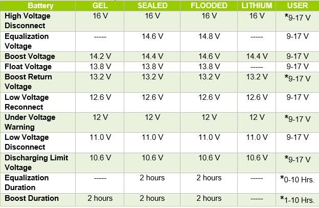
Equalization charging voltage: An equalization voltage is one you will most likely never see. It occurs roughly every 20 days, and it temporarily over-charges your batteries to desulfate the battery cell. This helps with the battery cell health and allows them to last longer. In this case of the controllers in Model 2.5.3, the equalized voltage will vary based on the battery type you are using. In this case, you can also set the equalization voltage, which is beneficial for certain batteries that require a customer set parameter.
Boost charging voltage: A boost charge is a majority of what you will see when your battery is being charged. This is what does the majority of the job. As you can see it will vary from each battery type and in this specific controller the user can set their voltage level.
Float charging voltage: A float charge is used when the battery is full to prevent overcharging. A float charge will still charge a battery, but reduce the voltage and current equal to the batteries natural discharge rate, which depends on the battery bank size.
Low voltage Reconnect + Disconnect: This only applies to controllers that have a load terminal, which will be discussed in the next section. The low voltage disconnect is the battery voltage level at which the load cuts off. The low voltage reconnect is the battery voltage level where the load turns back on.
Additional Features
Outside of the things mentioned above, some controllers have extra features that can be utilized. I will go through each one.
Load terminal: The load terminal comes with some controllers and allows you to attach a DC load to the controller, rather than having to attach it to the battery. It is usually noted with a light bulb symbol;A lot of time this is utilized for the timer function. You can program the load to turn on at sundown and off at sunlight. This is particular useful for lighting.
LED Indicators: The LED Indicators are used to give the user a basic idea of how their system is working. As you can see in model, a green light indicates the controller recognizes that the panel is hooked up and the system is functioning normally.
LCD Display: An LCD display can display different characteristics of your system and give you a more accurate portrayal of what is going on in your system than from the LED lights. This controller in particular will have icons that show what is happening in your system. It also displays numerical values for the voltage and amperage that your system is producing. Keep in mind, not all controllers have an LCD display and this is usually included on more expensive controllers.
Remote Display:
Model 2.5.4

A remote display is essentially just an LCD display, but with portability included using an RJ45 cord.
We carry a variety of charge controllers each with different features that sets them apart from one another. When choosing which charge controller is right for you keep the following in mind. If you like to know what the system is producing throughout the day we recommend choosing between the Adventurer, Voyager, Rover and Commander. The Adventurer is ideal if you are looking for a flush mounted controller. The Voyager is ideal for humid or rainy locations. If the controller will be mounted outside then the Voyager is the one for you. The Rover and Commander offer load terminals and a PC Monitoring Software. The PC Software allows you to customize the controller charging parameters and load terminal. We recommend the Rover or Commander if you like knowing every little detail about your solar system. If you just want something simple without all these extra features choose the Wanderer. One of the most important features when choosing a controller is making sure it can charge the type of battery you have. All our controller are capable of charging Sealed, Gel and flooded batteries but if you will be charging a Lithium battery only the Voyager and Rover are compatible.